History of GDSCC
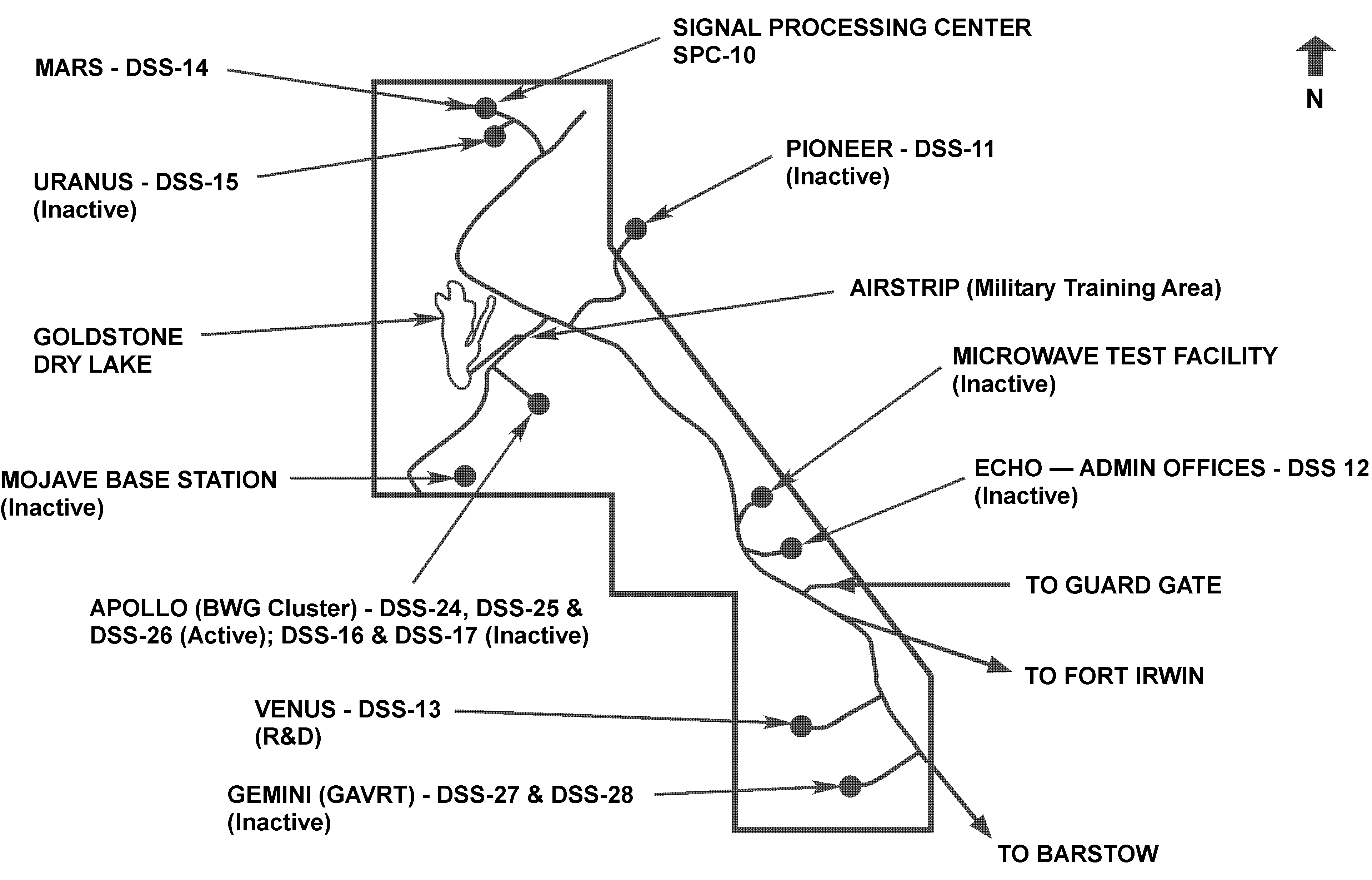
Goldstone was the first site chosen for a Deep Space Station.  The location was selected because it is remote from power lines and free of interference from commercial radio and television transmitters, which can impede reception of the very weak signals sent by the spacecraft. The remote location of the Mojave Desert in California, near the ghost mining town of Goldstone, was determined to be an optimal location for this new space communication platform. Thus the Goldstone facility was conceived and, in 1958, construction began on the Pioneer Deep Space Station (DSS-11) antenna.
Goldstone began its operations for NASA by tracking the Pioneer probes to the Moon; this milestone was followed by 40 years of high-performance service and research and development. Goldstone will continue to play a vital role in communication with distant spacecraft as new and more frequently launched NASA and international missions require support in the 21st century.
History of the Goldstone Antennas
Pioneer Station DSS-11
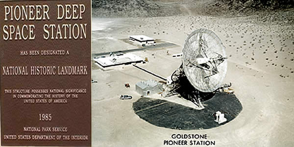
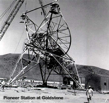
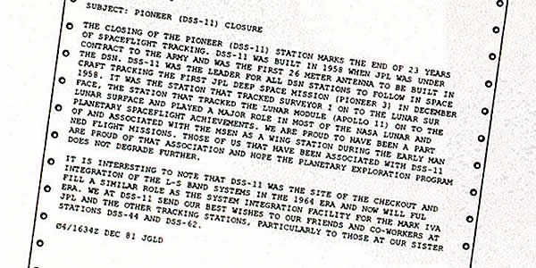
The Pioneer Station (DSS-11), a 26 meter polar mounted antenna was the first deep space antenna to be constructed at Goldstone. Completed Dec.1958 in time to support the Pioneer 3 mission, DSS-11 became the proto-type antenna for the Deep Space Network and went on to track a variety of NASA missions including all Pioneer spacecraft, the Echo Balloon projects, Ranger, Lunar Orbiter, Surveyor, Apollo, Helios, Mariner, Viking and Voyager. A Manned Space Flight wing was built at the Pioneer site to support the manned space flights of the Apollo program. DSS-11 was officially mothballed in 1981 and was declared a National Historic Monument as the first deep space antenna in the Deep Space Network (DSN) in 1985
1959
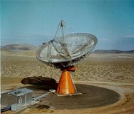
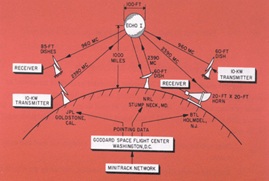
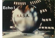
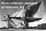
The original Echo antenna was a 26 meter (85 ft) Azimuth/Elevation design and was first used in support of Project Echo. NASA’s Project Echo was a communications experiment between the antennas at Goldstone developed and managed by JPL, the large horn reflector antenna at Holmdel, NJ developed and operated by Bell Telephone Research Laboratories, and a 100 ft. balloon in orbit around Earth. Both facilities were equipped with transmitters and receivers.
Venus Station DSS-13
The original Echo antenna was a 26 meter (85 ft) Azimuth/Elevation design and was first used in support of Project Echo. This antenna provided our first radar observations of the planet Venus. In 1962, the Echo antenna was moved to a new site six miles away at the southern edge of Goldstone. Eight 50-ton hydraulic jacks were needed to lift the structure onto a supporting undercarriage; the actual move occurred over a period of one week. The antenna was renamed the Venus Antenna in honor of the Venus Radar Experiment and designated as DSS-13.
1962
Completion of the new Echo antenna a 26 meter HA/DEC “polar” antenna. Following completion of the new 26 meter antenna, the original 26 meter AZ/EL antenna was moved to a new site and renamed “Venus” and designated as DSS-13 (Deep Space Station 13)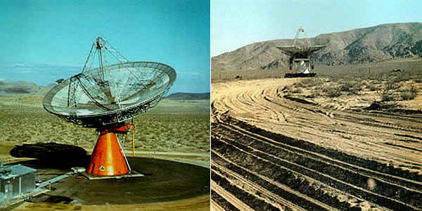
1963-1966
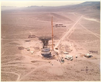
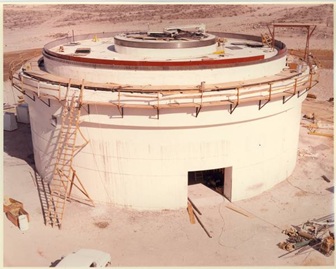
DSS-14 during construction phase 1963-1966
Construction of the DSS-14 Azimuth/Elevation 64 meter antenna started in October 1963. Designed and built by Rohr Corporation this antenna was completed in time to receive its first signal from space in March 1966. That signal was from the Mariner 4 spacecraft, a mission to Mars. DSS-14 became known as the “Mars” antenna and its location as the “Mars” Site. This antenna was the first of its size to be built as part of NASA’s Deep Space Network with identical antennas built later in Spain and Australia.
  |
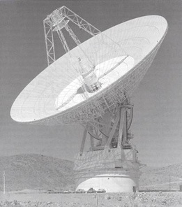 Completed DSS-14 64 meter Mars antenna with single cone configuration |
1966-1969
Apollo – DSS-16 Completed in 1966
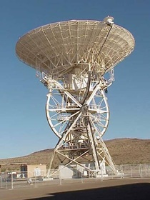
This 26-meter (85-ft.) diameter antenna was originally designed as part of the Manned Space Flight Network (MSFN) managed by Goddard Space Flight Center. At the completion of the Apollo missions this site was designated as part of the Satellite Tracking and Data Network (STDN) and used for tracking Earth-orbiter satellites, most of which are in orbits between 160 and 1,000 kilometers (100 and 630 miles) above the Earth. The X-Y mount allows the antenna to point low on the horizon to pick up the fast-moving Earth orbiters as they rise into view. The maximum tracking speed was three degrees per second. The 26-meter antennas were originally built to support the manned Apollo missions to the moon.
 Apollo 11 Mission, Lunar Module, American Flag and Buss Aldrin, July 20, 1969 |
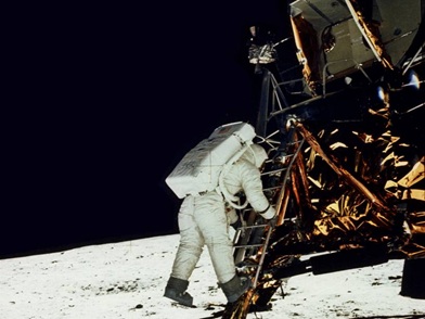 July 20, 1969. Edwin “Buzz” Aldrin steps onto the moon, photographed by Neil Armstrong during the Apollo 11 mission |
Echo Station
Conversion of the 26-Meter Antenna to 34 Meters
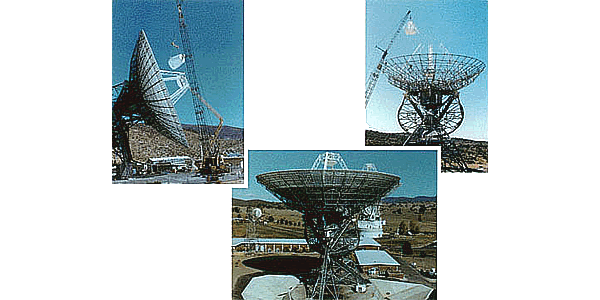
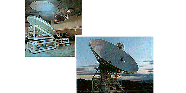
After the landing of the Viking spacecraft on Mars in 1976, the principal thrust of solar system exploration shifted to missions to the outer planets; i.e., Jupiter, Saturn, Uranus, and Neptune. It thus became important to modify the Deep Space Network to reflect the new mission set. The first step in this process was to convert a subnet of 26-meter antennas to 34 meters. This new diameter was chosen as a practical engineering limit that could use most of the existing structure of the 26-meter antennas. The choice was made to convert the Spain and Australia 26-meter antennas that were collocated with 64-meter antennas, and the newer of the two 26-meter antennas at the Goldstone Echo site.
The montage opposite shows various stages of the conversion. The photo in the upper left is the Goldstone antenna at the Echo site in its final stage of completion; the new dual S-X feed cone is being installed. The conversions were completed in 1979.
DSS-16 Shuttle Missions
Closure of the Pioneer Station
1984
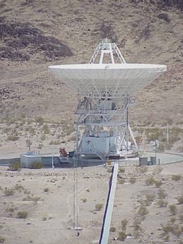
Uranus – DSS-15
1988
DSS-14 64-70 meter upgrade
The Mars Site is the home of the largest antenna at the Goldstone Complex. The Azimuth/Elevation type DSS-14 Mars antenna was upgraded to a 70-meter (230 ft.) diameter in 1988. This was to increase the sensitivity in support of the Voyager 2 spacecraft and its encounter with the planet Neptune. Standing 24 stories tall, 230 ft across and weighing 7.2 million kilograms (16 million pounds) this antenna’s immense diameter allows it to be the most sensitive of any equipment at Goldstone. The rotation portion, weighs nearly 4 million kilograms (8.4 million pounds), floats and moves on a thin film of hydraulic oil about .25 millimeters (.010 inches) thick. Despite its size, the antenna, with its complex electronic equipment and unique mechanical systems, is a precision instrument capable of communicating with spacecraft at the edge of the solar system such as Voyager 1 which is over 16 billion kilometers (10 billion miles) away from Earth and the most distant human made object in the universe. Besides being used to support many of JPL’s deep space missions, the high gain and multiple frequency capability of this antenna makes it an extremely valuable tool for radio astronomy and radar experiments.
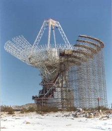 1988 during 70 meter upgrade |
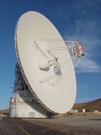 70 meter Mars Antenna |
New Beam-Waveguide Antenna at the Venus Research and Development Site
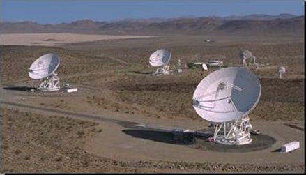
This 34-meter multifrequency antenna (DSS 13) at Goldstone was completed in 1991 at the Venus research and development site. It is the first antenna for deep-space communications to use a beam waveguide to route microwave energy between the main reflector and a room located in the basement. In this way, many feeds and amplifiers can be placed in a laboratory environment and be illuminated selectively by means of a rotating microwave mirror.
This antenna has a surface accuracy of 0.40 millimeters root-mean-square and will be used to perform characterizations and demonstrations of high-frequency technology. The Network has evolved from being able to provide communications with spacecraft at 960 megahertz to 2300 to 8450, in consonance with approved use of these frequencies for space to Earth by the World Administrative Radio Conference (which makes these frequencies available to NASA, when requested). The new antenna will be used to carry out the necessary developments to extend the frequency range to 30,000 megahertz.
Apollo Valley – DSS-24, DSS-25 and DSS-26
The Beam Waveguide Cluster
The 34-Meter Beam Waveguide (BWG) Cluster of three antennas was constructed from 1992-1996. These antennas were the first DSN operational antennas to utilize the beam waveguide design that moves weather sensitive electronic equipment into an underground pedestal, instead of a centrally mounted feed cone structure. The use of the underground pedestal allows for easier repair, maintenance and upgrades. These antennas are equipped to handle the communications needs of a large variety of deep space missions. In addition, these antennas may be arrayed together with the 34-Meter HEF antenna to provide the equivalent communications performance of the 70-Meter antenna.
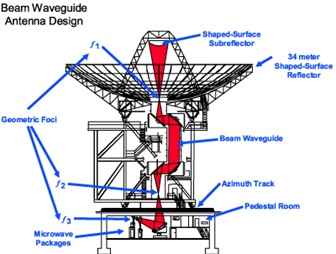
This design uses five precision radio frequency mirrors to reflect radio signals along a beam-.waveguide tube from the vertex of the antenna to the equipment room in the pedestal located below ground
Gemini – DSS-27 and DSS-28
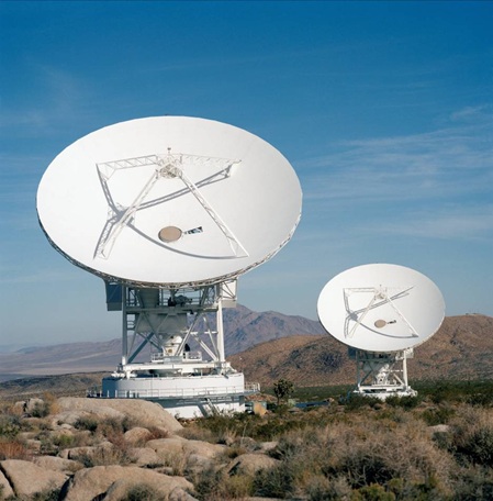
In a departure from the traditional method of naming a station for the first mission supported, this site is named for the twin stars in the Gemini constellation. The twin 34-meter Azimuth/Elevation high speed beam waveguide antennas were originally built by JPL for the Army and were transferred to NASA in 1994. The first mission supported was the Solar Heliospheric Observatory (SOHO), a cooperative mission between NASA and the European Space Agency (ESA). DSS-27 (in the foreground) is used today as part of the Deep Space Network and DSS-28 has been turned over for use as part of the GAVRT project (Goldstone Apple Valley Radio Telescope).
Signal Processing Center – 10 (SPC-10)
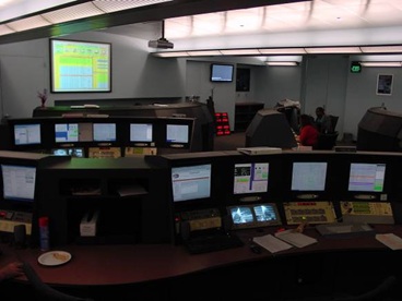
Renovated under ITT Corporation from April 2004 through May 2005 this Operations Center is staffed 24 hrs a day and 7 days a week. All antennas on the Goldstone Complex are remotely controlled from this facility providing uplink and commanding support while receiving critical information from robotic spacecraft exploring the universe. Goldstone also supports science through Solar System Radar (GSSR) as well as Radio Astronomy.
